Installation
Branches requires a -12V/+12V power supply (2x5 pin connector). The ribbon cable connector must be aligned so that the red stripe of the ribbon cable (-12V) is on the same side of the module's power header as the "Red stripe" marking on the board. The power consumption is 10 mA on the +12V rail and 1 mA on the -12V rail.
Controls
Branches consists of two identical sections called Bernoulli gates. An internal connection routes the input of section 1 to section 2 – unless a jack is connected into the input of section 2.
The Bernoulli gate
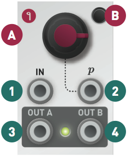
Upon receiving a trigger on its IN input (1), the module tosses a virtual coin: if the outcome is heads, the trigger is sent to output A (3); if the outcome is tails, the trigger is sent to output B (4).
The probability knob (A) and the associated CV input (2) change the odds of the "heads" and "tails" outcomes. In extreme settings, the outcome is no longer random - causing the module to behave like a voltage-controlled switch.
Toggle mode
In toggle mode, the module associates the "heads" and "tails" outcomes to a different pair of decisions: "continue sending the trigger to the same output as before" and "send the trigger to the opposite output". As a result, when the probability knob (A) is set to its maximum value, the trigger will alternate between outputs A and B.
Press the switch (B) to enable or disable the toggle mode.
Latch mode
When the latch mode is enabled, an output (3) or (4) stays at +5V until the other output gets activated.
Hold the switch (B) for more than 1s to enable or disable the latch mode.
Toggle and Latch settings are kept in memory even if the module is powered off.